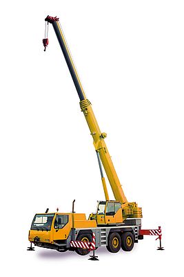
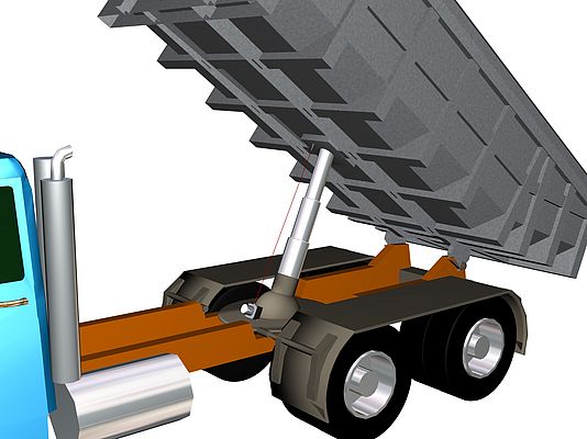
Displacement measurement in a hydraulic cylinder is a challenging task since a reasonable solution cannot often be easily found. For example, for truck-mounted cranes a load torque limiter is required in order to comply with health and safety regulations. Previously, the crane could only be operated when the hydraulic supports were fully extended. Today, a displacement measurement on the hydraulic cylinder can enable dynamic load torque limitation. Previously, this measurement could only be resolved reliably with some reservations. Micro-Epsilon Messtechnik has provided a completely new approach to displacement measurement of hydraulic cylinders.
The selection was previously restricted to three different methods for measuring the stroke movements of hydraulic cylinders. If the displacement measurement was already considered during the design, a magnetostrictive sensor could be integrated in the cylinder. For subsequent attachment outside on the cylinder, draw-wire sensors or magnetic or optical measuring rods or tape measures could be selected.
Previous methods
Magnetostrictive sensors are designed so that the measuring element is in a tubular sensor housing. This is always somewhat longer than the respective measuring range. The evaluation electronics are located on or in the cylinder base at the rear end of the sensor. For magnetostrictive sensors, a magnet in the piston is used as the position transmitter. As these sensors are designed to be pressure-proof, they can be integrated in the cylinder. Adjusting the sensor for the application is fairly straightforward, for example, by modifying the bar length. However, a bore in the piston rod that the sensor tube can be immersed in is required for operation. The greater the stroke movement of the cylinder, the deeper this bore has to be. In the case of large cylinders, for example for hall gates, this means that a bore in the metre size range may be necessary. Vertically boring a cylinder piston in this size range and without tilting is a major challenge. Rather than an integrated displacement measurement, a draw-wire sensor can be mounted on the outside of the cylinder. This method can be easily achieved, providing measuring ranges of up to a few metres. However, in harsh environments in which cylinders are frequently used, the draw-wire sensor can only be used with caution as dirt and mechanical loads may destroy the sensor over the long term. This limitation also applies when using optical or magnetic measuring rods. Here, the measuring rod is also installed on the outside of the cylinder. A grid applied to the bar is scanned optically or inductively. As this sensor is also outside on the cylinder, it is susceptible to soiling.
Due to these limitations , the two companies Sensor-Technik Wiedemann from Kaufbeuren and Micro-Epsilon from Ortenburg have developed an alternative solution. Both companies have many years of experience in the field of sensor systems.
Integrated draw-wire sensors
During development, particular attention was paid to the sensor being suitable for harsh environments and that no significant extra costs are incurred for the integration of the sensor to larger cylinders.
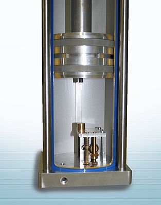
The co-developed solution is based on the draw-wire sensor, which is integrated inside the cylinder. Here, the sensor is completely protected from external influences. The sensor is positioned at the bottom of the cylinder and the measuring wire is attached to the bottom of the piston. A particular challenge here is the design of the sensor and the signal routing to the outside, as a bore hole in the cylinder hosuing is always a weak point. With pressures of up to 600bar in the cylinder, leakage is a risk that must be prevented.
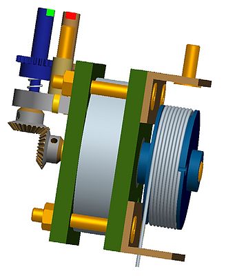
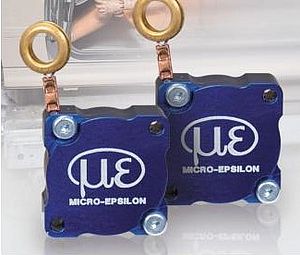
As well as the housing, the essential elements of a conventional draw-wire sensor are the spring, the drum, the measuring wire and a protractor as sensor element. A housing for the sensor can be dispensed with in this application, as the cylinder takes over this function.
Each movement of the piston causes a rotation of the wire drum. The rotation movement is divided using a gearbox onto two shafts with different rotation speeds. A magnet is positioned on each shaft at the bottom of the cylinder, whose positions can be measured by external, magnetic angle sensors. Using a suitable gearbox, each combination of the magnet positions only occurs once across the complete measuring range. The sensor therefore shows the characteristics of an absolute encoder. Micro-Epsilon was able to contribute a lot of expertise to the development of the sensor design and function of a draw-wire sensor.
Non-contact signal transmission
Due to the high pressures, the cylinder walls consist of relatively thick metal. A magnetic signal transmission through these thick walls is not suitable for measurement requirements. Due to the experience of Sensor-Technik Wiedemann in pressure measurement technology, a solution was found for this without having to weaken the design of the cylinder. At those points where the two gearshafts reach the bottom of the cylinder, the steel is tapered and a special membrane is welded on. A magnetic signal transmission with sufficient quality is achieved using this membrane. Using FEM calculations, the minimum possible wall thickness was determined.
The electronics on the outside were designed extremely flat and can easily be attached to the bottom of the cylinder. The electronics are available with cable or connector output. 4–20mA or a CAN interface are provided as output variants.
Application areas
Due to the draw-wire sensor, the system can easily be adapted to different cylinder lengths and diameters and to many different operating conditions.
The new wireSENSOR WDS-TZ10 is ideal for cylinders with a lifting height from 0.5m up to approx. 15m. The lubricating oil in the cylinder surrounds the draw-wire sensor. This functions as a lubricator for the sensor and provides a longer service life. This method is also suitable for cylinders without piston rods due to the hooking of the measuring wire. Cylinders with this type of displacement measurement are ideally suited to harsh environments and in mobile machines.
The TZ10 is an appropriate supplement to the magnetostrictive method for short cylinder strokes.
Author: Thomas Birchinger, Product Management Draw-wire Sensors, MICRO-EPSILON MESSTECHNIK, Ortenburg, Germany


