The recently deployed fifth generation (5G) wireless mobile communication technology is expected to be completely standardized by 2020. It will satisfy the ever-growing demand on wireless data transmission.
For starters, 5G is expected to improve the overall system capacity by several hundred times than existing technologies and increase the overall system throughput. 5G will offer higher spectral and energy efficiency while minimizing system latency. Unlike its predecessors, 5G will be introduced over several frequency bands. Lower frequency bands which are sub 6 GHz are heavily populated and have limited available bandwidth. Hence, to meet 5G requirements, several frequency bands at millimeter-wave (mm-wave) have been proposed and approved in most of the developed countries. This includes 24GHz to 29.5GHz, 37GHz to 42.5GHz, 47.2GHz to 48.2GHz and 64 to 71 GHz.
Establishing a reliable communication link at mm-wave bands for cellular applications offers great opportunities and poses several challenges. The mm-wave band provides wider bandwidth, compact antenna size and miniaturized dimensions.
However, the main challenges from moving to mm-wave bands are high atmospheric signal losses, shadowing, and high cost of system components. The attenuation of the signal at mm-wave mainly depends on the propagation distance, weather conditions and operating frequency. Shadowing is another important source of signal loss.
These losses introduce a challenge for antenna engineers to develop efficient, steerable, and high-gain antennas that help to overcome these losses to establish high quality communication links at mm-wave frequencies. Hence, 5G mm-wave antenna base stations are expected to use a combination of beamforming and MIMO technology. Beamforming is needed to provide beam-steering abilities as well as to provide a highly directive beam towards mobile phone users, MIMO technology can be used to increase the overall capacity of the system by increasing the data rates by transmitting several data streams to a user. This is referred to as single MIMO (SU-MIMO) and by serving multiple users simultaneously, itis referred to as MU-MIMO.
Developing such antennas and RF front-end solutions for 5G mm-wave base stations that are able to deliver both high-gain and beam-steering functionalities are highly complex and expensive due to the high cost of elements used in the system design, such as phase shifters.
Introducing the new approach to designing and producing new 5G beam shaping lenses
In order to meet the demands of 5G mm-wave, a different approach is needed to cost-effectively produce antenna base stations, like beamforming and MIMO technology. Shifting from an active phased array of mechanically steerable technology to passive, non-parts will introduce lower production costs of the antenna technology and later reduce the need for maintenance.
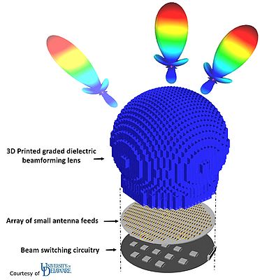
With XJet AM ceramics NanoParticle Jetting technology, researchers at the University of Delaware tried this different approach and developed a new passive lens antenna to be installed on top of an array of small antenna feeds. The array of antenna feeds was connected to the beam switching circuitry.
The development of this new beamforming lens introduced new challenges for example, the capability to scatter the mm-wave in any angle with minimum loss of energy. The outcome was a 3d printed spherical ball (marked in blue in the scheme below) designed to serve multiple beams over nearly the entire hemisphere (-90°<ø<90°) while supporting wide frequency bandwidths from Sub-6GHz up to 110GHz suitable for base stations (with new 5G bands) and for high capacity millimeter-wave backhaul links (E-Band - up to 110GHz).
The spherical ball was designed to include many cavities. Each cavity is located on top of the antenna feed and then serves as wave guide to the correct angle in the hemisphere. This enables the support of simultaneous multi-beams.
Looking for the ideal material
Once the design of the lens was made, the next challenge was to find the best material that would introduce minimal interference and loss of energy. After checking several materials, Zirconia (ZrO2) was chosen due to its remarkable, almost flat dielectric constant of Dk=32.2 with very little loss across the full-listed spectrum.
Several tests on Zirconia vs. PBG (measured and simulated) were conducted to show that the transmission of Zirconia was 0 to -10dB, while PBG materials showed inconsistent transmission varying from 0 to -44dB.
Once sintered, the Zirconia displayed another important feature with its outstanding, durable, wear-resistant, hardness, and toughness: it served for many years on top of the beam antenna without requiring any maintenance.
Once finalizing the design and choosing the correct material to withstand the listed requirements, the production technology needed to meet the requirements of the specially designed ball:
- Hollow cavity & holes - to create the mm-wave guide.
- Relatively small and lightweight – to be able to withstand mechanical forces that might be emitted on the installed antenna, reducing its footprint to be small and lightweight yet still enable higher durability and less maintenance of the installed base station.
- Simple 1-part assembly; no moving parts.
- Outstanding durability, wear-resistance, hardness, and toughness
- High accuracy and fine details
- Exceptional sharpness – any uneven surfaces will internally scatter the wave inside the wave guide; hence, sharp, smooth internal and external surfaces are critical
XJet Advantages:
Engineered ceramic printing in production worlds means being able to achieve high accuracy with fine details, exceptional sharpness while not harming the remarkable density of the ceramic materials.
Working with XJet NanoParticle Jetting (http://xjet3d.com), jetting nano-particle Zirconia materials layer on layer, enabled the University of Delaware team to achieve the requested results.
In their tests they got:
- High accuracy and fine details – while building the inner cavities or waveguides.
- Exceptional sharpness to reduce energy loss or internal absorption.
- Remarkable density (99.9%) which results in flat homogeneous dielectric properties (Dk=32.2)
- High productivity for multiple, customized parts that can address different frequencies. Hence, it took the same time on the same tray to produce different antenna sizes to address different frequency needs.
Using traditional ceramic injection molding technology, it would be impossible to remove materials from inner cavities, thus making it impossible to manufacture the required, complex design. Additive manufacturing produced the design one layer at a time.
By Rafie Grinvald, Vice President of Product Management & Marketing at XJet
