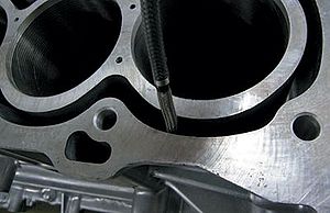
One reason we humans can navigate our surroundings so effectively is that we see the world through two forward-facing eyes and our brain constantly compares the two scenes as we move. It detects where each object is located relative to the scene from the other eye. Figures 1a and 1b represent what you see when you close your right eye and left eye respectively. The lateral shift of what we view from one eye to the other is called the parallax effect.
This lateral shift is inversely proportional to the distance from the viewer to the object—meaning the closer it is, the greater the difference in its position from each eye. This also means the “Z” distance is inversely proportional to the lateral shift. Our eyes work with our brains to achieve an understanding of how far away various objects are (a table, a chair, a car, the moon) and how large or small they are. This is fundamentally how stereo measurement works.
Use of Stereo Measurement in Industrial Videoscopes
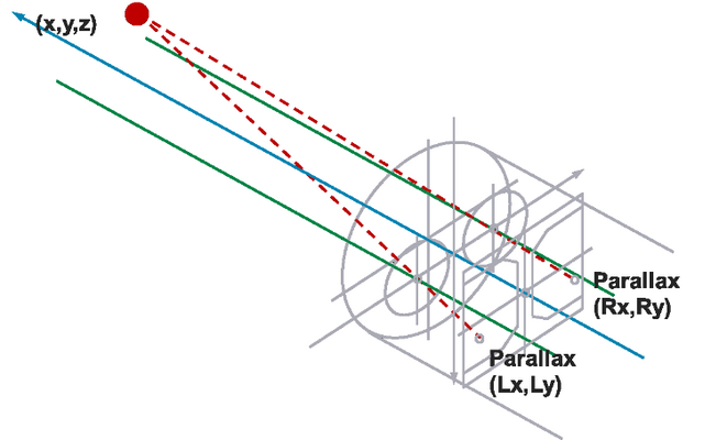
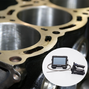
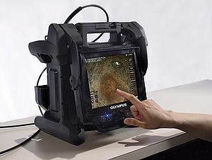
Industrial videoscopes are devices used in the field of remote visual inspection (RVI). Stereo measuring videoscopes have a charge-coupled device (CCD) imaging sensor and processor (the “brain”) that operate with two lenses (the “eyes”) in the scope’s tip adaptor. The lenses are offset a known distance from each other. Parallax is used to determine the “Z” distance of a point of interest from the two lenses. Figure 2 demonstrates this triangulation.
Prerecorded Data and Measurement Precision
Comparing the parallax of two images can be used to calculate how far away a point of interest is, but the precision of this calculation relies heavily on the prerecorded metrics of the optical system. This means that for a stereo measuring system, the distance between the two lenses in the tip adaptor must be known to a very fine degree.
Videoscope tip adaptors are subjected to very strict tolerances during the manufacturing process. However, their components are housed in an incredibly tight space. The tip adaptor holds two lenses in an area smaller than 6 mm (0.236 in.) or even 4 mm (0.157 in.) in diameter. Because of these miniature sizes, the tolerances are much smaller than are physically possible to control in a manufacturing scenario, and any variance outside the tolerances has a greater effect. Since extremely small physical variations in the components can have large implications on the parallax effect, accounting for and calibrating against these variances is the best strategy.
One way to overcome this limitation is to consider the metrics of the CCD, since it is also part of the parallax calculation. To increase the measurement precision, the distance of the CCD from the lenses and if it is slightly rotated relative to them can also be input into the system. After this is done, that lens system (housed in the tip adaptor) is considered mated to that CCD (housed in the end of the scope). Although videoscope tip adaptors are removable and replaceable, once mated, the stereo lens tip adaptor should always be used with the same videoscope for the sake of higher measurement precision. This is called “one-to-one matching.”
Advantages of Using 3D Modeling
The two major considerations for any measurement system are accuracy and precision. 3D stereo measurement in RVI is no different. So far this discussion on improving accuracy and precision has focused on the videoscope itself. The final piece of this process is the inspector.
With a stereo measuring videoscope, the actual measurements performed are based on points that the inspector places on the two images. The images through the two lenses are almost identical, except for the lateral shift. When the user picks a point on one of the images, the videoscope picks a point on the other image that corresponds to the same point on the object being measured. It then uses all the prerecorded metrics data to calculate the measurement.
Much research and design has gone into 3D stereo measurement to make it as accurate and precise as possible. Because the actual measurement is based on points picked by the inspector, this is where a bottleneck in the measurement system arises. If the inspector is not fully aware of the shape of the object being measured, they may put the point in the wrong place.
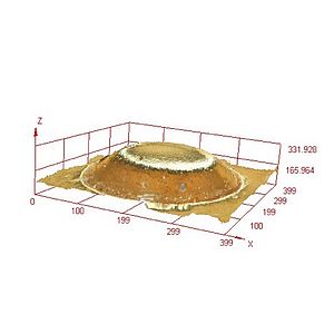
Industrial videoscopes are now able to generate 3D models of target objects. The videoscope calculates the distance from the tip adaptor to every pixel on the image. Using the tip adaptor as the anchor in space, the videoscope can then generate a 3D model.
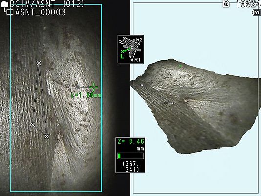
In addition to providing a better understanding of the target object’s shape, the 3D model can show inspectors at a glance the areas of interest that are important to focus on. In Figure 3, there is a 2D image and a 3D image that were taken to identify and measure undercutting in a weld inspection. Undercutting is what happens when there are areas next to the weld that are lower than the base material. It is caused by the intense heat generated by the welding process. In Figure 3, the base material is the flat section to the left of the weld.
Increasing Efficiency with Color Mapping
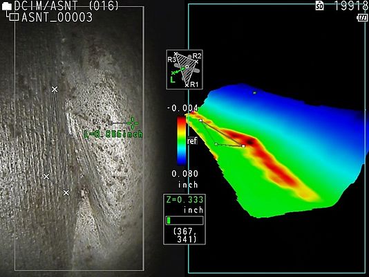
One way to detect undercutting is to measure the depth at points all along the weld. You can see in the 2D image that there is a white triangle to the left of the weld. This triangle establishes the reference plane. When the depth measurement is performed, they are done in relation to this plane. That is, measurements are made to see how much above or below this plane are the measurement points. If the inspector uses 2D and 3D images alone, multiple measurements are required. A much quicker way to do this is a method called color mapping. Since the videoscope has already calculated the distance values for each pixel on the image, it theoretically already “knows” if there are any spots below the reference plane. With color mapping, this data is used to produce an image (Figure 4), which shows the area below the reference plane in red. The inspector can now focus the measurement on the red areas to locate the deepest undercut value. In this way, 3D modeling can greatly improve the speed of certain measurements.
A videoscope that measures precisely is effective only if it measures the correct point. Advances in 3D modeling enable videoscope inspectors to make more reliable measurements because they can better perceive the actual shape of the object they are measuring. They now know where the point is in real space and are more aware of what the videoscope is measuring. Using features such as color mapping, inspectors can further improve their efficiency, seeing clearly at a glance the critical areas to focus on.
