The German large scale demonstration project of the FP7 funded European project GRID4EU (*) (www.grid4eu.eu), which is led by the RWE Deutschland AG, addresses the development, implementation and field test of an autonomous grid control system in the Medium Voltage (MV) level. The high share and still massively increasing amount of distributed generation, predominantly wind and photo-voltaic sets new challenges to the DSOs. In order to provide hosting capacity to integrate these resources huge investments in grid infrastructure are required. Grid operation and grid observation become more complex since power flows become less predictable. At present in Germany there are hardly any surveillance facilities or grid automation in place in MV networks. The basic project idea addresses an extension of the automation level of MV networks based on an autonomously acting and switching grid control system as an industrial solution for network operation. The following objectives are targeted:
- Integrating an increasing number of decentralized energy resources (DER) in the MV and underlying Low Voltage (LV) networks Avoiding "classical" network expansion measures
- Achieving higher reliability, shorter recovery times after grid failures (FDIR)
- Avoiding unknown overloads and voltage violations
- Fulfilling the needs of surveillance and remote-control in MV networks
- Reducing network losses
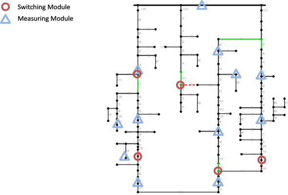
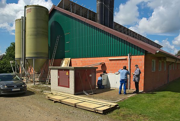
The demonstration project is built up in the area of Reken, located in North Rhine-Westphalia, Germany. The considered grid is well selected since it shows even today a balance between installed generation power and maximum demand, with forecasted further increase in DERs to be connected. The grid area of Reken consists of around 120 secondary substations where a total number of 18 substations are equipped with Switching (seven) and Measuring Modules (eleven). Switching Modules can operate the switchgear of their secondary substation whereas Measuring Modules provide only measurements. Autonomous switching provides the possibility of dynamic topology reconfiguration which is a new concept of operation.
Module positioning
One of the key factors of the project was the optimization process to evaluate the location and the minimum number of modules in the MV network. To evaluate these locations two approaches have been applied separately. A set of heuristic rules could be evaluated depending on the network topology and on the location of DERs. These rules give practical recommendations where to set separation points in the network for switching between different operational scenarios. The second approach, known from network planning, uses a heuristic optimization technique which starts with a completely meshed network structure and adjusts iterative separation points until the overall topology becomes radial. Both methods lead to very similar results where typically switching modules enable separating larger loops. Measuring modules are mostly placed at some far-away laterals or in the areas of high DER penetration.
System architecture
The complete system structure and the core algorithms of the system were developed and tested by the TU Dortmund and ABB. All modules are based on the RTU500 family from ABB. The implementation was done in the RTU500 integrated PLC (Programmable Logic Controller, IEC 61131). The main idea is to implement an autonomous system which is able to manage the grid without a high level SCADA system. To do that, two different approaches are possible:
- Centralized architecture, where the 'intelligent' functions are concentrated at the master module in the primary substation. Slave modules in the field perform only measurement acquisition and execution of control signals.
- Decentralized architecture, where all functions are implemented on the modules in the field and the system is working as an agent system.
Both approaches have their pros and cons and finally a hybrid solution was implemented where the slave modules are responsible for acquisition and transmission of measurements, fault indications and breaker status signals. Local load forecast and local state machine functionalities are also outsourced. The local state machine is in charge of supervising the local limits for current and voltage. In case of a limit violation, this information is sent to the master module. The local forecast provides the most probable trend of the power flow for the next few hours.
The master module is implemented on the RTU placed in the primary substation Groß Reken. Its tasks are supervising the underlying system and reacting to some particular operational situations. The main function blocks of the master module are:
- State machine: determination of the overall system state (secure state ⇔ faulty state)
- Optimization: finding the loss-optimized target topology based on the actual situation/forecast and creating the switching program to reach this topology
- Switching program management: executing and supervising of the switching program
- Forwarding information to the SCADA-system
The Fault Detection, Isolation and Restoration (FDIR) is implemented as a decentralized task. Our hybrid system architecture anticipates, beside the standard communication from master to slave, also peer-to-peer communication which enables neighbored slave modules to exchange data among each other. This dataflow is used to control the FDIR algorithm.
Simulation results in the test lab
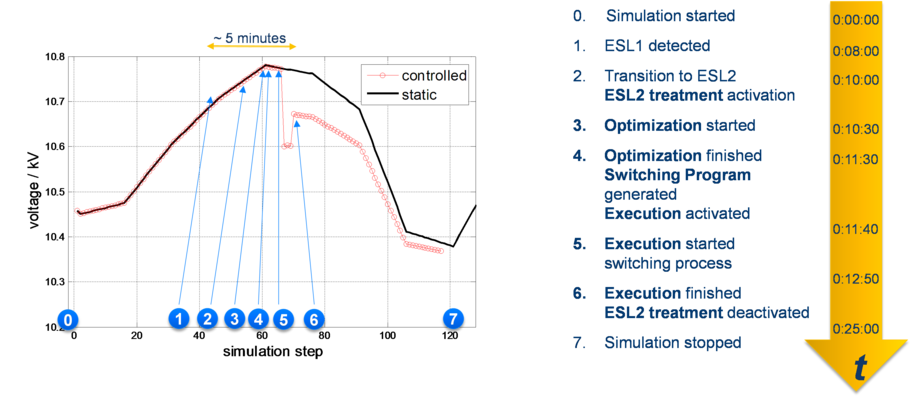
In order to prepare the control system for future field operation a laboratory test bed involving used RTUs and a software network emulator has been implemented. A hardware-in-the-loop simulation allows testing and adapting the control system software which is running on the automation hardware. Figure 2 shows exemplarily a voltage violation situation which is solved after a few minutes by the system with some few switching operations.
Field test in 2015
The field test will be carried out in 2015 divided in four phases:
- Recording of measured values and signals
- Semi-automatic switching step 1
- Semi-automatic switching step 2
- Autonomous switching
Phase one already started end of 2014. Beginning with phase 2 switching actions will be done in the grid, first under full control of the control center staff, in phase 3 with only approval and finally full autonomous switching in phase 4.
Conclusion
The German Demonstration of the European project GRID4EU is focused on the basic idea of an autonomously acting and switching grid control system in the MV level. In summary this article gives an overview on the basic system architecture, the field implementation and first experience of the operational phase which continues until the end of 2015. Additional simulations show the potential of this solution and will be completed with an economic analysis in 2015.
(*) Acknowledgement: This work is co-funded by the European Commission under FP7, in the framework of GRID4EU project (grant agreement No ENER/FP7/268206).
By Peter Noglik, Principal Scientist, ABB AG, Corporate Research Center, Ladenburg (Germany)


